User Tools
This is an old revision of the document!
Table of Contents
Pinger Bearing
This page describes the math used to calculate our bearing towards the pinger using our hydrophones. A solution is derived in 2 dimensions to show how it works, then our final result is extrapolated to 3 dimensions.
Assumptions
Planar Wave
Imagine dropping a rock in the middle of a pond. At first the ripples look very circular, but by the time they reach the shore they look like straight lines. We assume that the wave front of the ping is planar, which basically means that even though the wave front is curved, the curvature is small enough from the perspective of the hydrophones such that the wave front actually looks flat. This makes our calculations a lot easier.
2D-Derivation
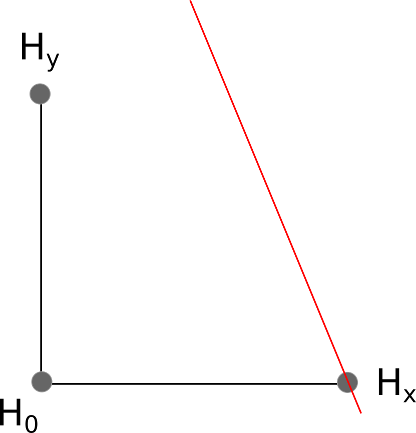
The speed of sound of water is defined as $c_s$. We have 3 hydrophones, located at the following positions:
$H_0$ is at location $(0,0)$
$H_x$ is at location $(x,0)$
$H_y$ is at location $(0,y)$
We shall simulate a wave traveling towards our hydrophone array. First, it hits $H_x$ at time $t_x$
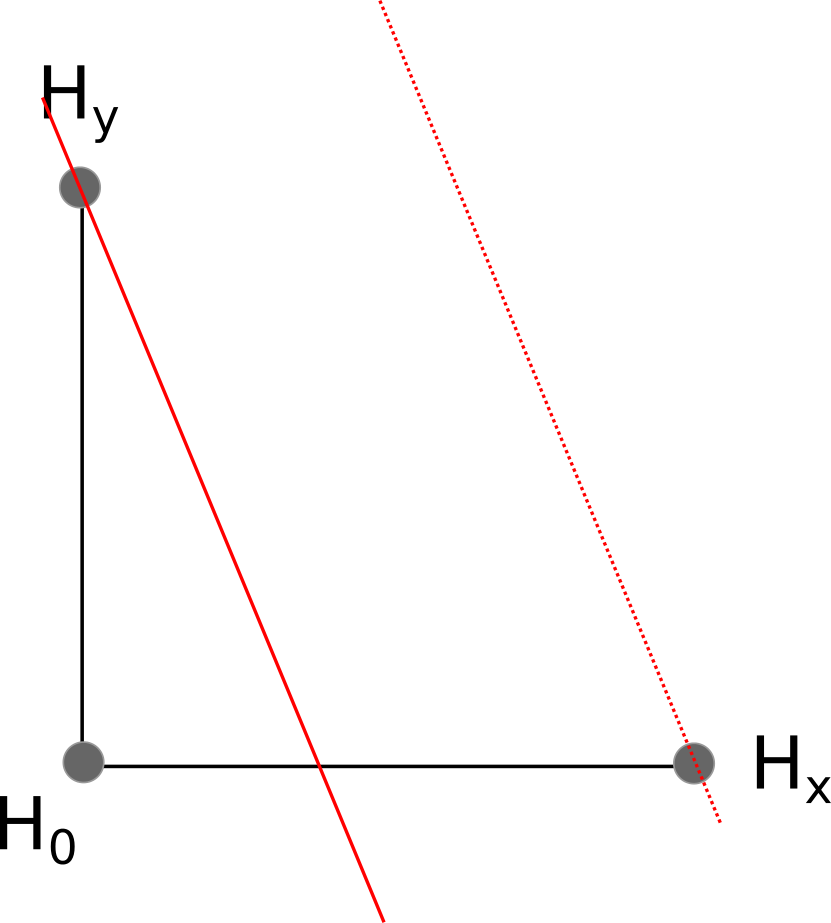
The wave continues, hitting $H_y$ at time $t_y$
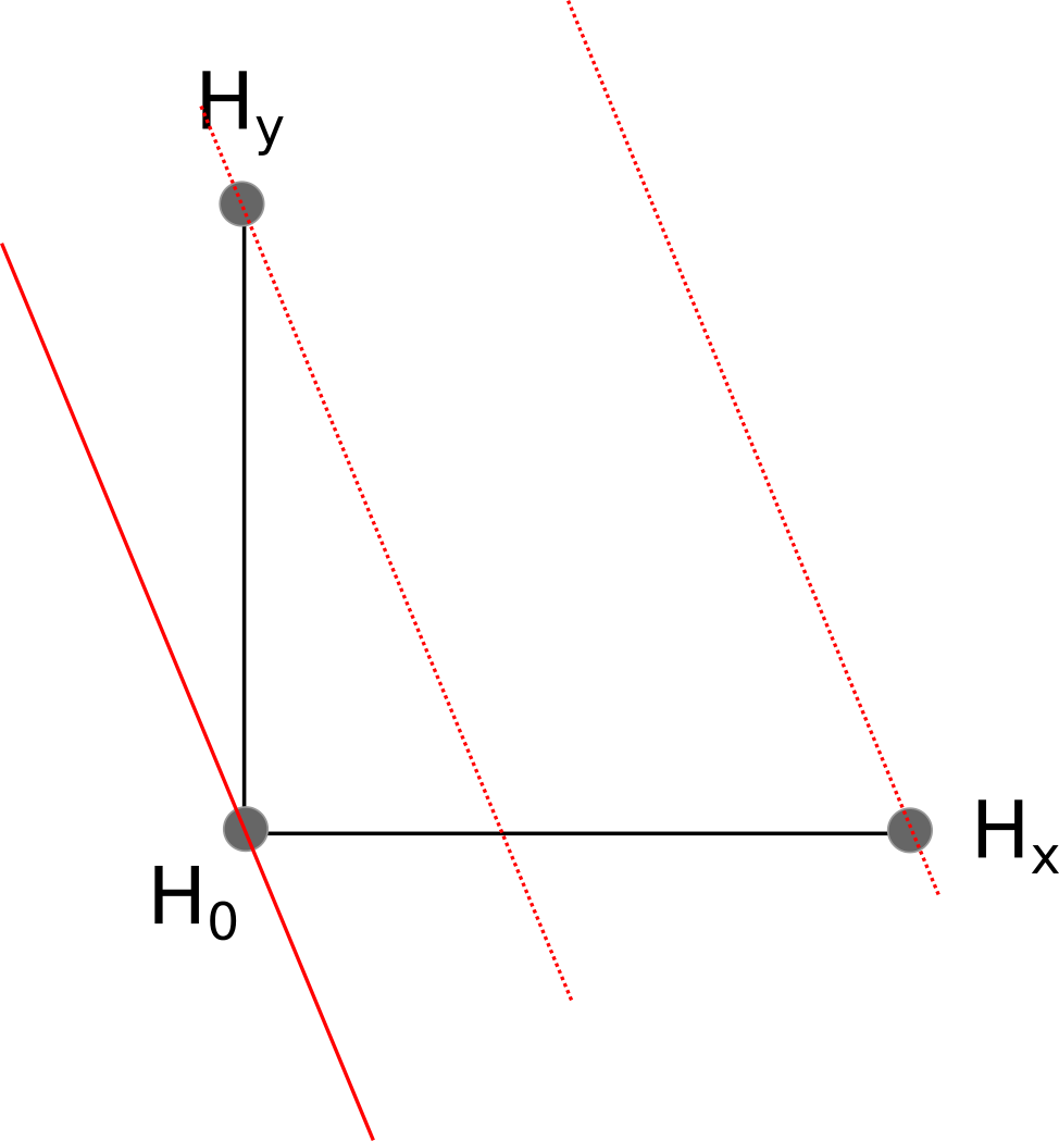
Finally, the wave hits $H_0$ at time $t_0$
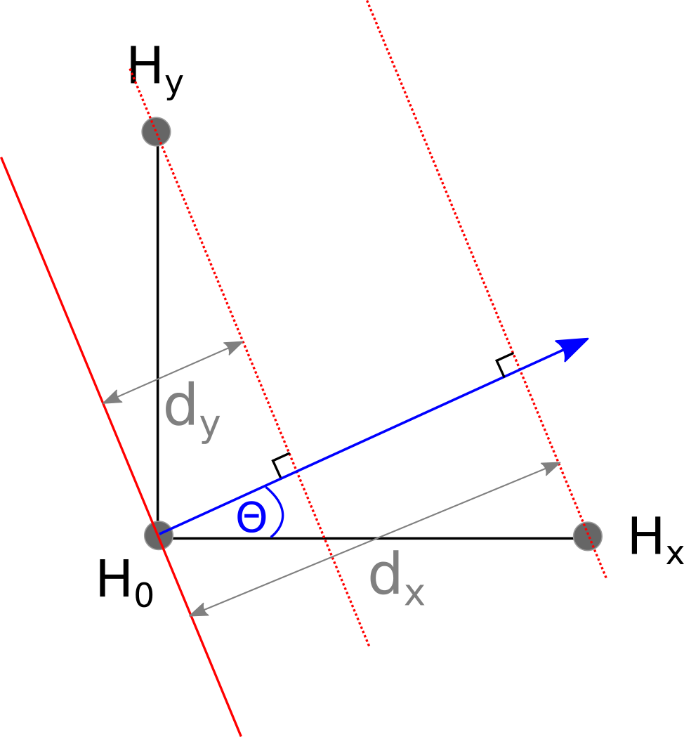
Because the wave emanating from the pinger hit $H_x$ before it hit $H_0$, we know that $H_x$ must be closer to the pinger than $H_0$. In fact, $H_x$ must be exactly $d_x = c_s(t_0 - t_x)$ meters closer to the pinger than $H_0$. Likewise, $H_y$ is $d_y = c_s(t_0 - t_y)$ meters closer to the pinger than $H_0$.
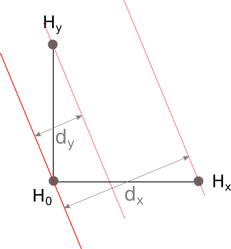
Our main goal is to calculate a vector pointing from the $H_0$ to the pinger. This vector is perpendicular to the wave front, and is shown in blue in the diagram below:
We can also describe the vector in $i,j$ notation: $$ \begin{bmatrix} \hat{i} \\ \hat{j} \end{bmatrix} = \begin{bmatrix} \cos(\theta) \\ \sin(\theta) \end{bmatrix} $$
Luckily, it is pretty simple to calculate $\hat{i}$ and $\hat{j}$: $$ \begin{bmatrix} \hat{i} \\ \hat{j} \end{bmatrix} = \begin{bmatrix} d_x/x \\ d_y/y \end{bmatrix} $$
Extrapolating this into 3 dimensions, we have:

