User Tools
Table of Contents
Primary System Design
Project Lead: Ryan Summers
Overview
The primary system design dissects the overall electrical requirements into three equally important tasks and then develops lower level projects to be completed:
- Provide safe and sufficient power to the submarine
- Provide correct and meaningful sensor feedback to the computer
- Provide a control bridge for computer-controlled devices (such as pneumatics and thrusters)
Power Design
The power system of the submarine can be divided further into two separate power systems:
- Thruster Power
- Bulkhead Power
The power case, which is an external compartment, contains all the relay and bussing of power to the various subsystems. As such, there should never be thruster power entering the bulkhead.
Both of the systems are fed by raw battery voltage, and they are under control of two separate relays. The bulkhead power should be fused at 20 Amps to avoid short circuits within the main hull, and the thruster system should be broken out to each thruster through a ganged fuse setup. Each thruster should be additionally fused (25A) to protect the battery and the rest of the electrical system from overdrawing current.
The main battery should be safely fused before being split into the two power systems.
For the bulkhead system, raw battery voltage is fed to a single power distribution block, which then in turn is fed directly to components that require power.
All devices that are connected to the CPU through a USB connection will have optional, magnetically-isolated 5V supplied off the USB hub. It is not mandatory that they make use of these supplies.
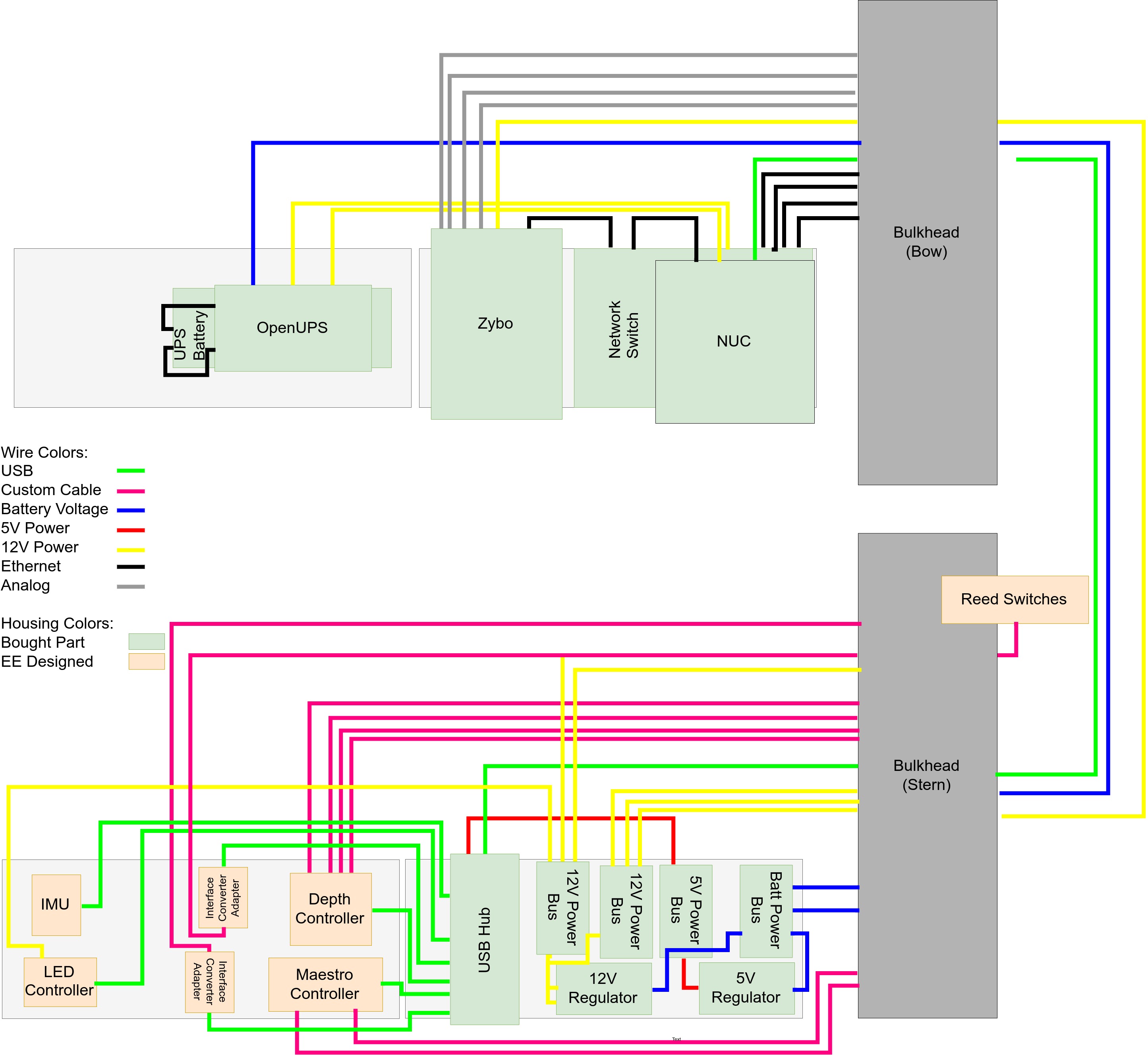
Below is the current architecture of the power system in the submarine:

Sensor Feedback and Control Bridging
Another important feature of the electrical system is to provide a means for the computer software to control various pieces of electrical equipment. Currently, the electrical system allows control of pneumatics and thrusters. Pneumatics are controlled directly as a ROS node running on the microcontroller in an external pneumatics compartment. Pneumatics are connected to the computer through a USB-to-UART interface converter. Thrusters are controlled directly through a USB servo controller. A ROS node runs directly on the computer and communicates with the thruster through a serial interface. The thruster controller will be moved to an external housing at a later date.
The final purpose of the electrical system is to provide sensor feedback to the computer system so that it has information about it's current orientation. To do this, two sensor systems have been created. The depth sensor system is composed of four high-precision depth sensors placed at four different points on the support structure of the submarine. These sensors penetrate into the bulkhead and mate with a depth sensor reading microcontroller. This microcontroller is connected to the computer through a USB-UART converter and runs a ROS node natively on the microcontroller. The IMU sensor system is composed of a single high-accuracy IMU sensor. This sensor provides yaw, pitch, and roll to the computer. A ROS node must be written on the computer to interface with the data provided by the IMU sensor.

Bulkhead Connections
Below is a preliminary diagram showing all electrical bulkhead connections. This diagram is not finalized and should be assumed as only an initial draft. Please confirm with electrical team before using.

Internal Layout
Below is the current plans for internal component layout and wiring. All drawings are to scale.