User Tools
This is an old revision of the document!
Table of Contents
Hydrophones
We use our hydrophones to locate the pinger in the pool, which can be utilized for localization purposes.
Introduction
The purpose of this page is to describe how the arrival times are acquired on a number of hydrophone channels. This documentation does not describe how that information is turned into bearings or how it is used in localization.
The arrival time calculations tend to be complicated by noise, which means that it is not possible to trivially detect rising edges. The ping can be thought of as an identical signal arriving slightly later on each of the hydrophones. In order to accurately calculate the time differences between each signal, a cross correlation is used. A cross correlation essentially slides one signal over the top of another, and at the point where the signals maximally overlap, the amount of shifting needed is equal to the time delay of the signal.
Further simplifications can be applied to the problem as well. By ensuring that the hydrophones are close enough, it can be guaranteed that the arrival time difference will never exceed one half wavelength. Therefore, the cross correlation only needs to be completed within +/- half a wavelength. The signals occur at a maximum frequency of approximately 40KHz, which means that the arrival time difference can never exceed approximately 12.5 microseconds. This means that the hydrophones must be spaced within 1.8cm of each other due to the speed of sound in water.
Now that the theoretical aspects are out of the way, the foundation of the problem starts to take shape. 1) Acquire signals on all four hydrophones (one reference and 3 along each X, Y, and Z axis) 2) Cross-correlate the X, Y, and Z axis signals against the reference to calculate time of flight delay.
The cross correlation step is simple mathematics. Note that cross-correlation boils down to multiplying individual points of two signals together and accumulating, so if the signals are big it can take quite a bit of time. We will discuss how to handle this later.
The main difficulty exists in sampling the signals. It is important that samples are taken simultaneously on each of the hydrophones and that the signals are sampled fast enough to ensure that the precision in time of flight is accurate enough (for example, at a sampling frequency of 1MHz, the time of arrival can never be more precise than a signal microsecond). Therefore, the system must be capable of simultaneously sampling four channels at a minimum rate of 1MHz.
Hardware
System Design
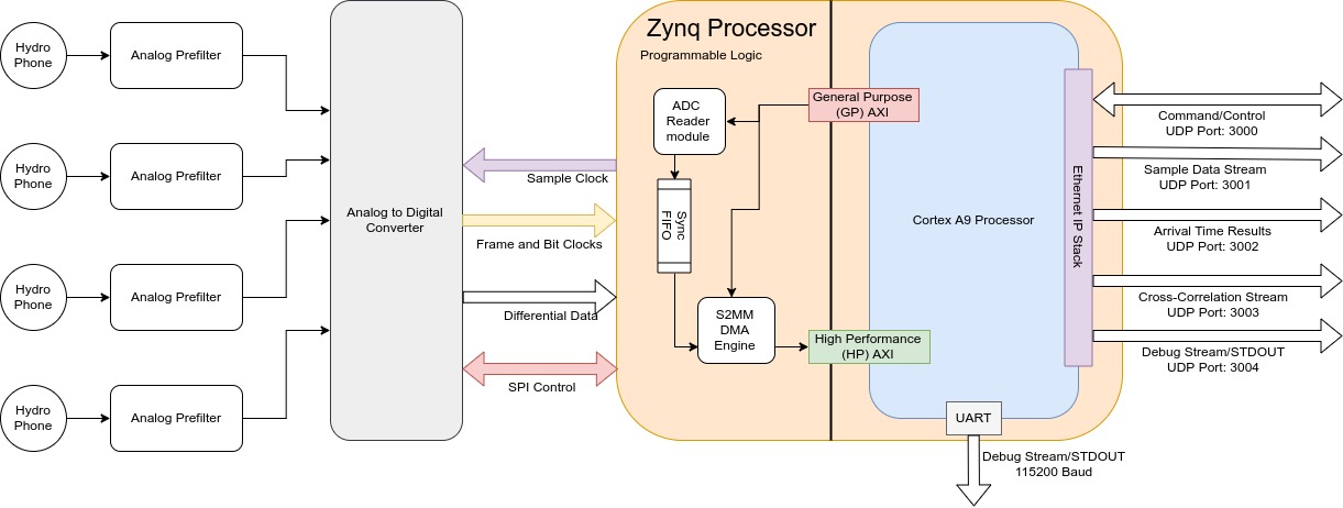
The hydrophones have small piezo sensors that output very small voltages as sound hits them. To be able to read them, the hydrophone signals are filtered with a 1st order bandpass and then are gained by approximately 40-60dB. After the signals are amplified, they are then passed to the ADC for conversion. The ADC samples the hydrophone signals at 5MHz simultaneously and outputs the converted information over a custom, parallel interface. This interface is differential and utilizes DDR. In order to read the ADC values, the Zynq SoC (System on a Chip) is used. The Zynq has a dual core ARM processor embedded in FPGA fabric. A custom Verilog module was created for reading the parallel interface output by the ADC. The data is then sent over the AXI4-Stream protocol to allow it to be transferred into the processor's RAM through the HP-AXI interface (AXI is a common communication protocol for custom hardware modules written in Verilog). In order to accomodate the high data rate of the analog measurements, the AXI stream is connected to a DMA engine. At this point, the data has been successfully transferred into the computer and the cross correlation can be performed. The below sections delve into specifics of each of the different design areas.
Analog Circuitry
The analog signal goes through a five-stage amplification and filtering process. First, the signal is sent through two gain stages, each of which apply an adjustable gain to the signal. After the signal is gained into a reasonable voltage range, it is passed through a low-pass filter and then a high-pass filter to result in a bandpass filter of the signal.
Once the signal has been filtered and gained, it is preprocessed for the ADC. In order to acquire more accurate measurements, the ADC requires signals to be differential. The analog signals are therefore put through a signle-ended to differential converter. Immediately before the signals enter the ADC, there is a low-pass anti-aliasing filtering. This filter guarantees Niquist criteria, which means that any frequencies detected in the sampled signal will not be aliases of higher frequencies.
